The life of construction machinery is not strewn with roses. The hardest life is for popular machines with the highest number of hours worked; as the number of hours worked increases, they are worth less and less, and their service is more and more limited, until eventually they end up in the bushes to rot. The large and very expensive machines are doing a little better, with their resourse depending mainly on the level of maintenance over the years. With any machine, however, there comes a point when we have to decide whether to go for a high-volume upgrade, or to let go and dispose of or scrap the machine so as not to unnecessarily feed the resources of the competition.
Construction machinery engines, as their heart, are a special component. In the space of 30-40-50 years, diesel engine technology has changed by a good 3-4 generations, and despite the fact that the industrial engine market is long-lived, servicing units that historically remember the 1970s has become a problem. The main sources of problems are in the first place, the reluctance of service centers to service old engines, the second is the limitations in the availability of spare parts, and the third is the increased failure rate due to the age of the engine itself.
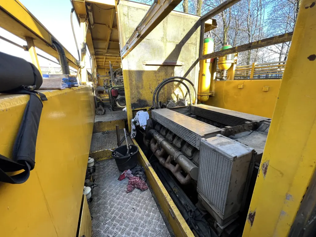
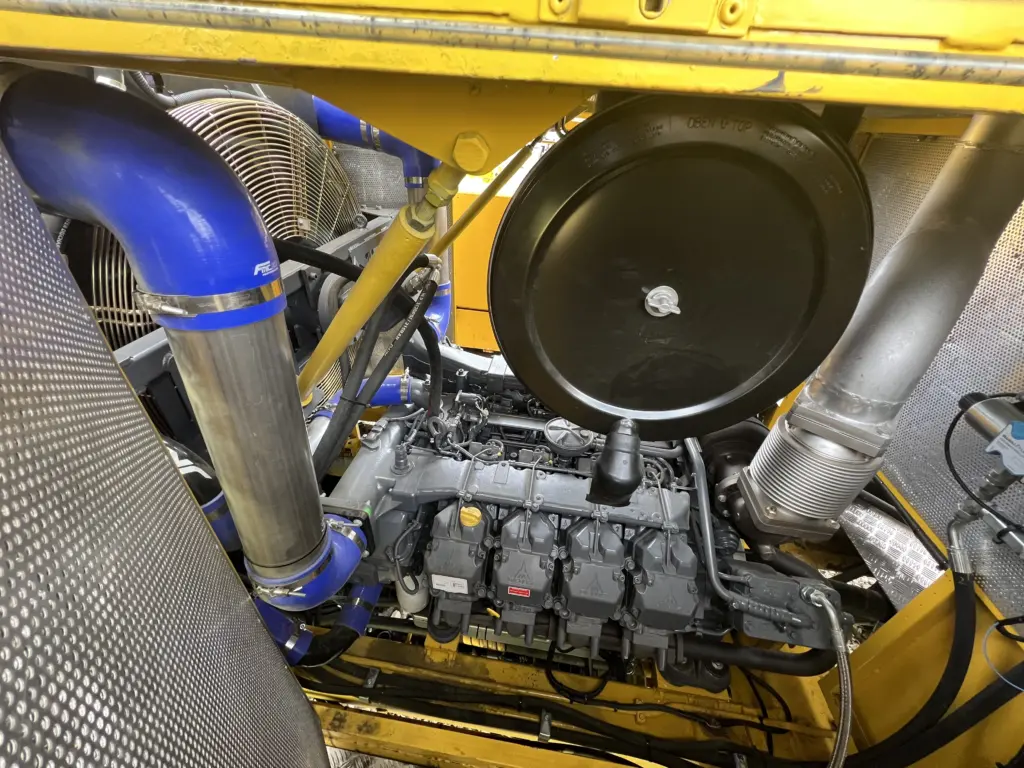
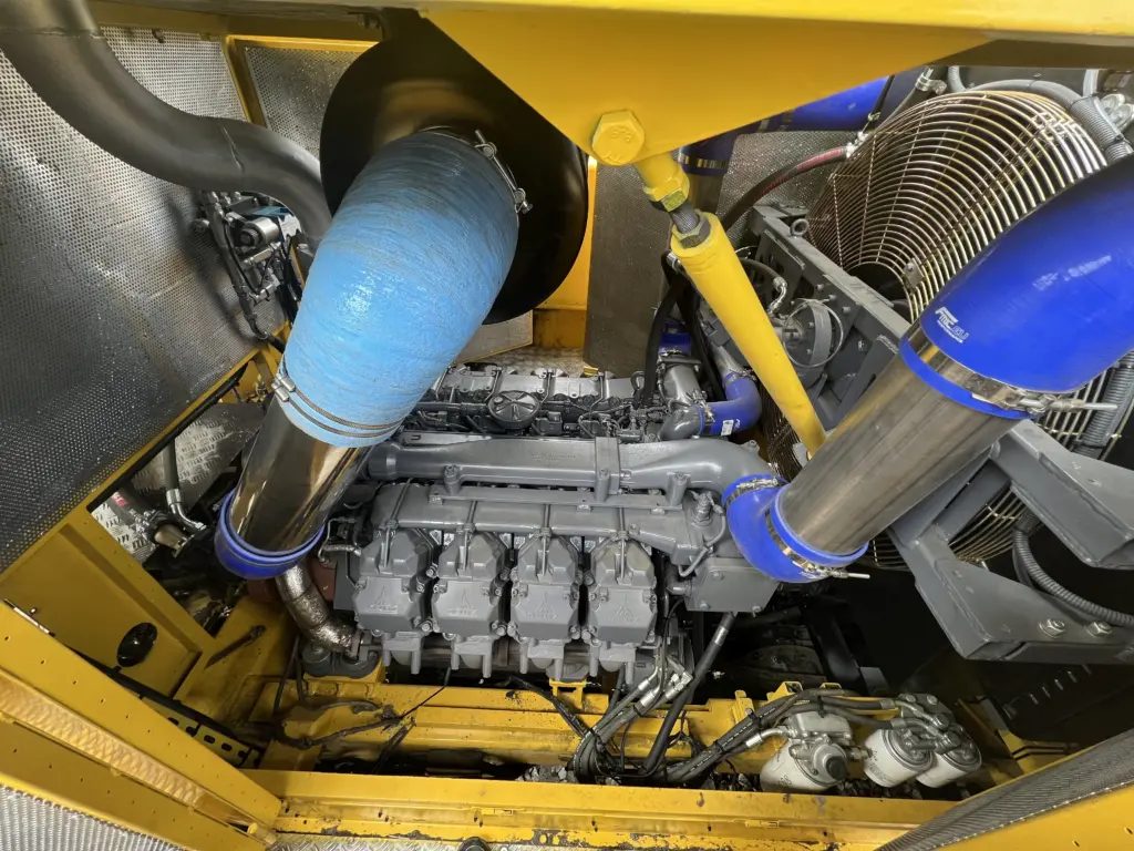
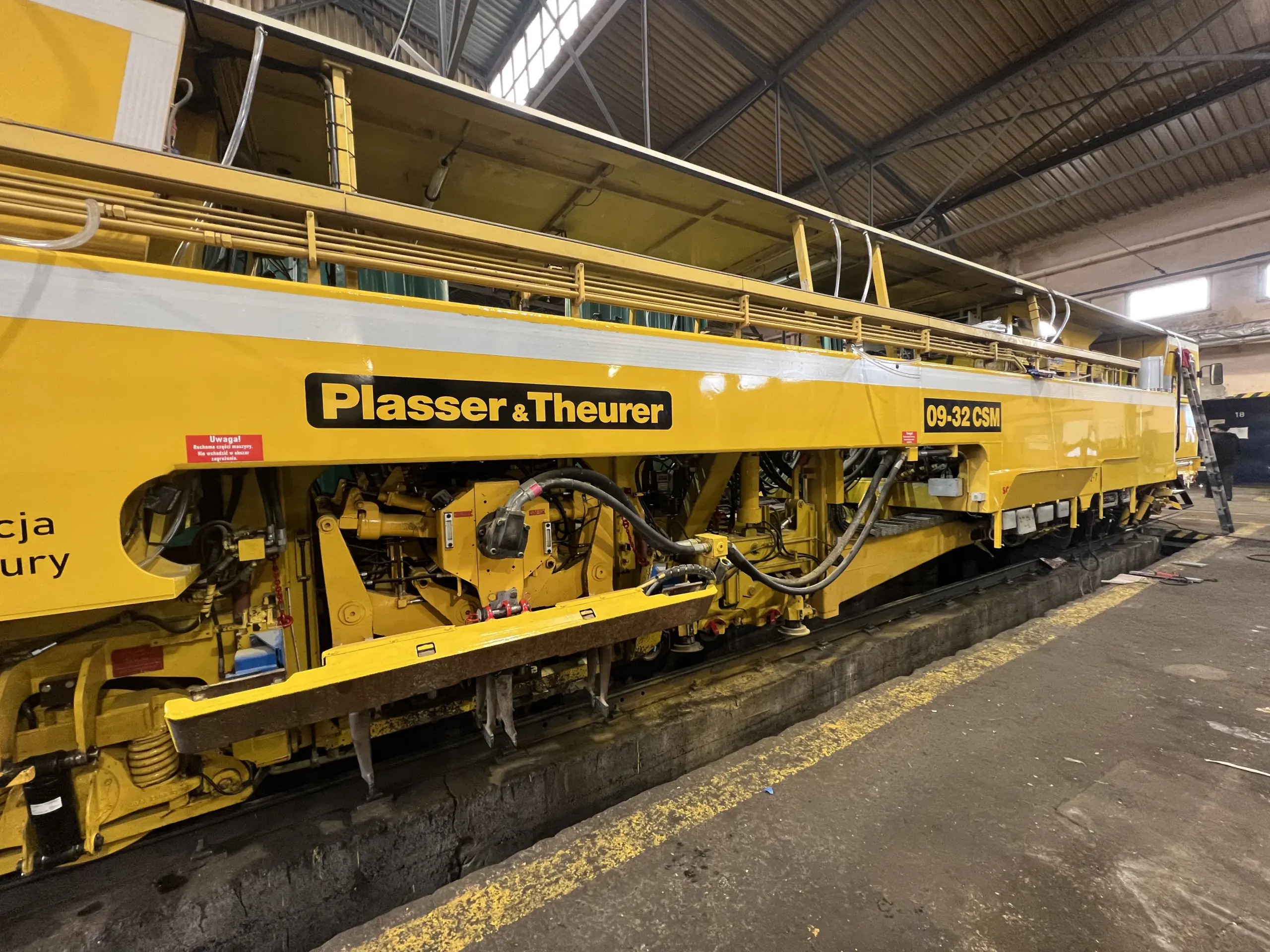
In early 2023 I had the opportunity to upgrade the engine of a Plasser&Theurer 09-32CSM track tamping machine, equipped with a Deutz BF12L413F engine, whose design remembers the 1970s. Deutz engines from the 413 family can definitely be considered very successful. To this day they still work in many machines, and just a few years ago I saw new copies of such engines being installed in mining machines manufactured in our country for eastern markets. The main argument for their use was precisely reliability and, thanks to air cooling, good compatibility with cold climates.
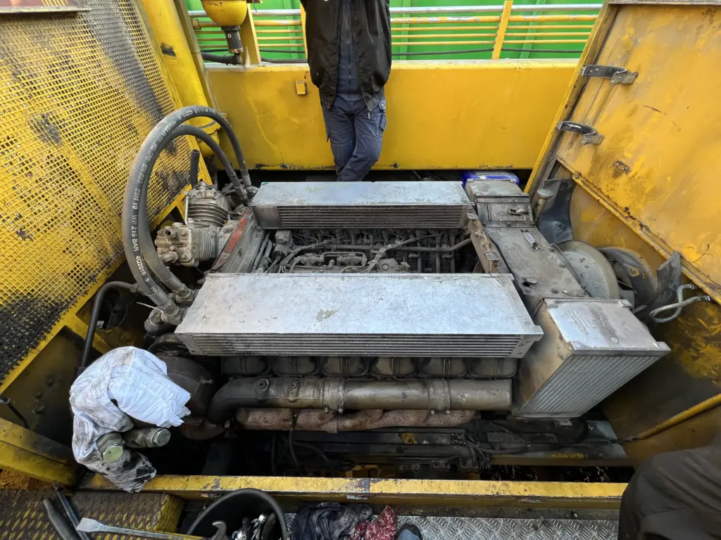
Why then replace such a unit with another? There are several reasons, and each defends itself very well. The first is what I would call the reluctance of service centers to service very old engines. As a mechanic I understand it well, burying such old equipment is always a risk that something will fail, and customers are not eager for complex solutions that generate high costs. As a result, it is sometimes better not to put your hands into devices that are followed by the risk of problems and customer dissatisfaction. The second problem is the lack of such units on the secondary market. Of course, on a European scale we will probably be able to find such an engine, but it will almost certainly be a unit in a state for a complete overhaul, which for a used unit must be carried out to a greater or lesser extent always. Especially because of the sheer costs associated with the logistics of replacing it in a machine such as a track tamping machine. The third reason is the very similar cost of buying from the manufacturer a factory remanufactured unit of the old and new type. The factory remanufactured Type 413 engine can still be ordered from Deutz AG as part of the X-change program, but its cost is essentially the same for the TCD2015V8, the company said. With the old type of engine, the cost of rebuilding the machine would fall off, but we would not solve the problems mentioned in the first place. In addition, analyzing the manufacturer’s data on the fuel requirements of the two units, a simple calculation indicated that if the machine works, the investment is likely to pay off in fuel costs alone within a few years. It is too early to verify this in practice, but there is no doubt that the efficiency of the TCD2015 engines stands at a completely different, higher level.
Who to partner with for delivery?
The decision to replace the drive unit with a newer one was made as early as 2021 and the comprehensive implementation of the task was undertaken by one of the authorized Deutz service centers in Poland. The whole story turned out to be a complete flop, and in retrospect, I know with certainty that they had no ability to deliver. This service did not meet any declared deadlines, and when we decided to inquire at Deutz’s headquarters for Poland, BTH Fast, it turned out that the engine we were waiting for had been ordered by the service from another source (unknown), contrary to company policy. In addition, the unreliable service decided to express its dissatisfaction with our intervention and we heard that we were sticking our nose into things that were not ours and broke the contract on time when its implementation should have been in the final stages… Given that in March 2022 we had on the shop floor a dismantled machine without an engine and poor prospects for carrying out the upgrade, the only and painful decision was the one to put the machine back together and postpone the whole operation for another year. Further cooperation in the delivery of the drive unit, we have started with Deutz AG’s main representative for Poland, BTH Fast. And this cooperation I highly praise. The reliability, timeliness and support of BTH Fast stand at a very high level.
Why work with an authorized Deutz supplier? We need to keep in mind that an upgrade such as the one under discussion is basically building a prototype that must work from the first time. In addition, everything must be designed, planned and prepared well in advance. It is not possible to build everything on the spot in kind, if only because the waiting time for some of the components is 3-4 months. In such a case, cooperation with an authorized manufacturer supplier, is crucial. First of all, in such cooperation, we have the opportunity to access all technical documentation, component characteristics, digital STEP models, which are indispensable in the design of installations and reliable information on the availability and cost of components.
What does it look like to buy an engine from Deutz AG?
This is where things get interesting. At first, I couldn’t understand why the cost of a brand new engine and a factory remanufactured X-Change are slightly different (the engine itself). In practice, it turned out that we could not purchase the engine new, because it involves buying an engine in a specification that meets current standards. That is, in practice, we would have to purchase a unit with at least a very expensive DPF-equipped exhaust system. There was neither time nor space (physically in the machine) for this. On the other hand, buying an engine from Deutz’s X-Change program, also comes with limitations. Namely, we need to order an engine with a specific serial number, in a previously produced specification. Just like ordering a replacement part. Here, the assistance of a Deutz representative is essential, since only he has access to information about the engines produced.
You have to look for compromises, especially since buying and replacing engine components is very expensive later. And so, instead of two smaller alternators, we are left with one large one, the air conditioning compressor must be “glued” somewhere, etc. Troublesome but acceptable. When we put together an ECU (engine control management unit) for an engine, we also need to verify exactly how it has been programmed, because it turns out that despite the presence of various functions in the specifications and on the diagrams, the controller you receive will not be equipped with some of them, or they will work slightly differently than expected. The consultants at Deutz, don’t know absolutely everything either, and the ability to ask the right questions and in the right way is key.
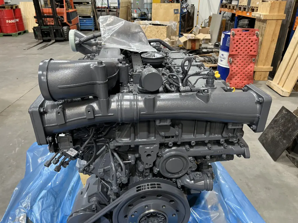
The engine itself from the X-Change program is indistinguishable from a factory-new engine. I tried to find traces of the use of any component that had signs of previous use, but to no avail. If the engine is equipped with a used block, crankshaft and possibly head housings, that’s all it has in common with engine reconditioning.
Problems and technical issues
In the case of this particular upgrade, two issues were the main sources of the problem. The first source of problems was the replacement of the air-cooled engine with a liquid-cooled engine and the second was the need to design a hydraulic cooling fan drive. The two problems merged into one main issue.
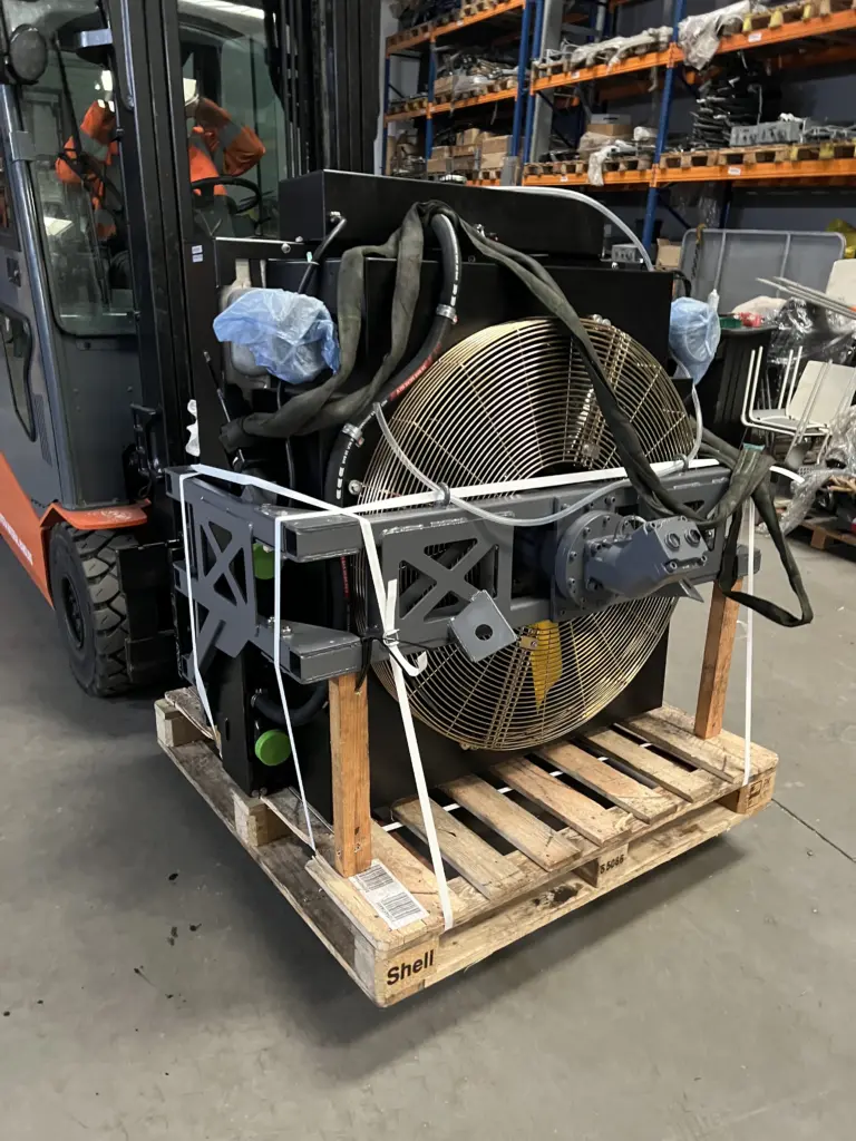
In the case of the CSM 09-32 tamping machine, both the front and rear of the crankshaft are used to drive the machine’s attachments. The rear of the crankshaft (flywheel side), is connected by a drive shaft to a ZF automatic transmission, which provides the machine with a transport drive. The front of the crankshaft, on the other hand, through the driveshaft, drives the hydraulic pump gears that feed the machine when tamping the track. A situation in which power from the crankshaft is received from both sides of the crankshaft is a rare configuration. Most often we have a radiator fan mounted at the front of the engine, and the radiator itself is mounted directly in front of the engine and supported by the same stringers. Due to the need to mount the engine radiator above the front drive shaft, a hydraulic drive had to be designed to drive the cooling fan. And this is where it gets interesting, because, the power requirement of the fan is at maximum engine speed almost 40kW! That is, the fan alone is responsible, under extreme conditions, for receiving about 10% of the power generated by the engine. The design of the fan doesn’t help either, as it is designed to be mounted on a motor, and thus is solid and heavy, weighing a good dozen pounds. The heavy fan included with the hydraulic motor is not suitable for mounting directly to the radiator, so I had to design an additional frame, which is a fan carrier and radiator support that will allow the radiator to be isolated from vibration. Despite the fact that the radiator assembly, the drive fan and the subframe, were designed as compact as possible, when they were placed in the engine compartment, there was 10mm of clearance left per side (this was, of course, in accordance with the design).
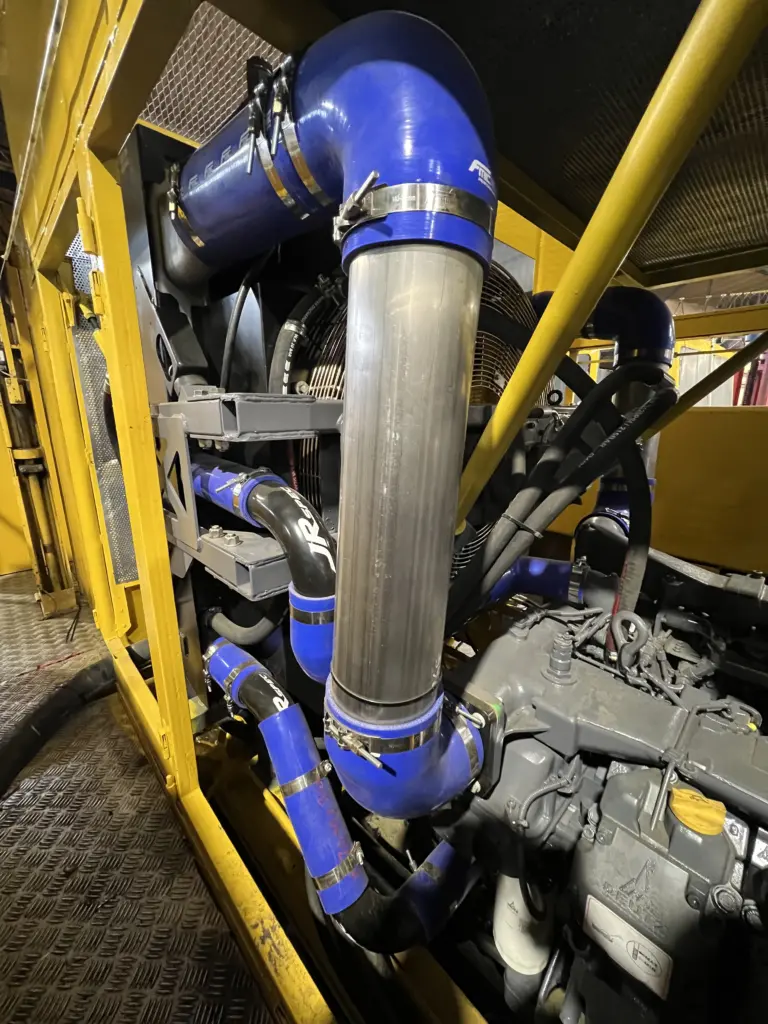
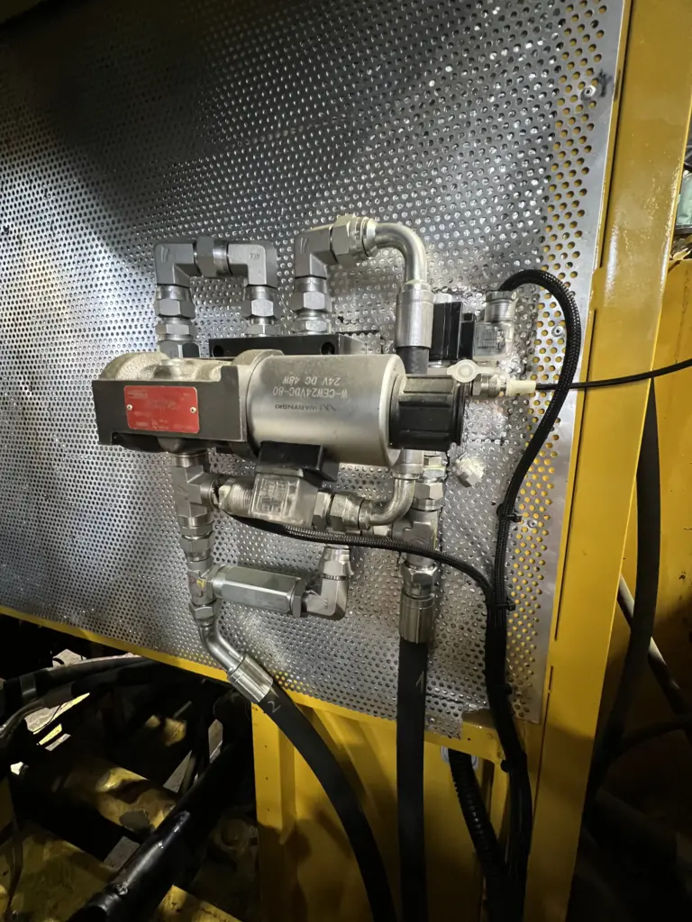
During the selection of a hydraulic motor to drive the fan, it turned out that the hydraulic pump with which the supplied motor was equipped, completely has no chance to cope with the task for which it was intended. Here experience was lacking both for me and my support at Deutz. The supplied gear pump has been replaced with a power attachment to receive more power from the engine timing and a corresponding Hydro-Leduc fixed displacement piston pump. The fan motor was also selected from this manufacturer’s offerings. The hydraulic drive control has a total of 3 gears. Idle, when all the pump output goes into overflow, gear 1 for which we can set a limited operating pressure, and gear 2 running at full capacity. In addition, the system works so that when the engine is extinguished, the fan is not braked by the pump and is free to decelerate. The idle gear was intended not to load the engine during startup, but in practice it is not needed and starting the fan in gear does not place a significant load on the engine. Second gear is also not essential. When designing such a system, I would once again stay with a single circuit with the possibility of limiting the pressure in the system (that is, the possibility of speed control). Hydraulic drive of the radiator fan, in addition to the disadvantage of complication, has the great advantage of providing the possibility of reducing the load on the engine with the work of the fan or, for example, providing the possibility of raising the operating temperature of the engine, which can also be advantageous. There is certainly some room here to look for savings in fuel consumption and reductions in emission volumes.
An interesting issue was the selection of a flexible coupling, working between the flywheel and the ZF transmission. Ordering the clutch entailed providing the manufacturer with data related to engine balance (or rather, imbalance), ZF gear characteristics and the like for calculations. The waiting time for the clutch was 16 weeks, and the cost was astronomical. In the end, we installed the component exactly as we should, thus fulfilling part of the engine manufacturer’s warranty requirements.
The troublesome part of the installation turned out to be the exhaust system. Mainly due to the lack of choice of suppressors that would be available on the market off the shelf. There are, of course, manufacturers with catalogs full of products, but waiting times of 12-16 weeks were unacceptable. It stood to reason that we made renovations to the machine’s original mufflers and they were returned to their place. I am least satisfied with this part of the installation. Everything works as it should, of course, but one could have gone ahead with soundproofing the entire system. In retrospect, the issues related to quieting the machine during such an upgrade would have been a much higher priority for me.
Integration of the new drive into the machine
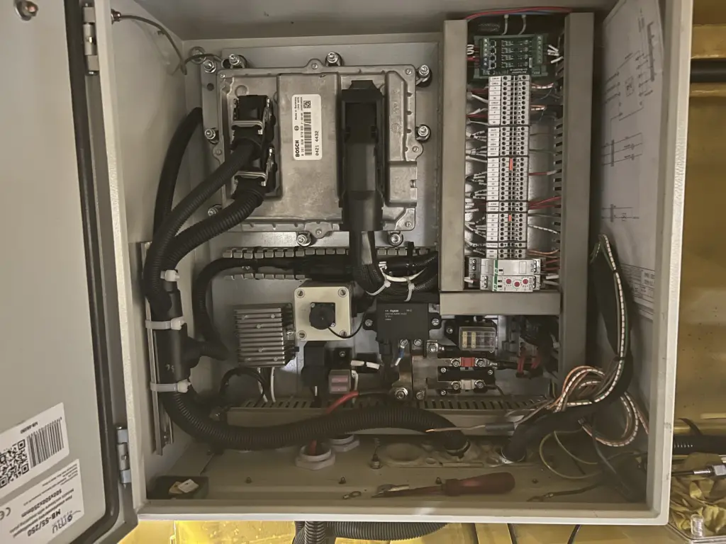
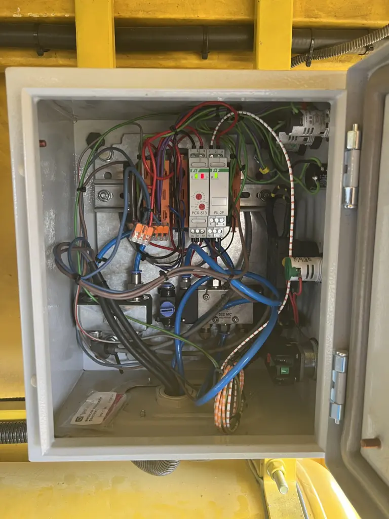
The speed control of the factory engine was implemented in a very simple way. Connected to the in-line linkage of the injection pump, there was a pneumatic actuator that controlled the revolutions, and a second pneumatic actuator that was responsible for locking the maximum engine speed for the machine’s working (boost) mode. In tamping mode, the engine speed is crucial because it is directly proportional to the speed of the shafts of the tamping units, i.e. it is responsible for the frequency of their operation. Engine RPM control must meet the functions – drive mode (full RPM range), boost mode (limited maximum RPM), and provide the ability to easily adjust the maximum RPM for boost mode. In addition, the machine has 3 points from which operators must be able to control the engine (simultaneously, for safety reasons) – two driving cabs and one tamping station. The system is seemingly simple, but in practice, realizing it using potentiometers instead of the existing pneumatic valves involved designing a dedicated electrical system and programming at least one microcontroller. Time was pressing and finding a person to design and make such a layout proved troublesome. At some point, I started looking for another solution, and this is the one I found, launched and successfully tested. Namely, I replaced the two pneumatic actuators responsible for controlling the rotation of the old motor with analog pressure transducers. One working in full range and the other, which had an additional potentiometer at the output, whose task was to limit the output signal, i.e. the amount of maximum rotation. Signals from the transducers were fed directly to the engine controller. It’s not ideal, but it has one big advantage. Thanks to it, the operators’ operation of the machine has not changed in any way and the factory levers for controlling the machine’s gas and mode switching have remained in place.
I hope you find the modernization described interesting. Of course, I have included above only a few of the very many technical details it involved. Trying to describe all of them would make few people patient enough to get to this point. If you are interested in the broader aspect of the whole process then, of course, I warmly invite you to contact me.
